

Electrical
AUV

Left to right: Gabe Piano, Seth Richard, Sachin Kumar, Maggie Wu, James Williamson, Rhea Deshpande, Yatin Gour, Aras Jahangiri, Kyle Lee, Jovan Sohi, Malachy Frey, Adam Teodosio, David Manhart, Hasan Mohammad
Not pictured: Salman Amin, Saim Hajini, Antoine Godin, Reid Pratley
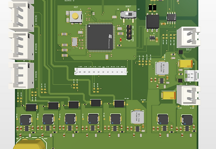
Main MCU
The onboard control system was redesigned by replacing the previous ESP32 with an STM32F7 standalone microcontroller. The new board includes a USB-to-UART converter, enabling wireless flashing through the onboard Jetson and eliminating the need to remove the electrical tray for software updates, significantly streamlining development and testing

Actuator Board
The Actuator Board controls all the servos on board the submarine. It allows each servo to be controlled with pinpoint accuracy.
Power Distribution Board
This year’s power distribution board was redesigned for cleaner organization, using breakout pins that allow each PCB to slot directly into the board for simplified power delivery without excess wiring. The system also incorporates TVS diodes to protect circuitry from voltage spikes and fuses to improve electrical safety under unforeseen conditions.


Kill Switch
The killswitch was redesigned as a standalone mechanical system that physically cuts power to the motors, improving reliability and reducing susceptibility to communication failures. Using 16-volt relays, it routes power from the LiPo batteries to each motor and is triggered by a magnetic reed switch, instantly disabling motor power while keeping critical onboard systems active.
Battery Management System
The battery management system is designed around a Texas Instruments BQ76952. This IC was chosen for its included ADC input, allowing for the use of an external current sensor, the ACS770-150U. The BMS lies on a custom designed PCB, built to handle the 16.8V 120A that can be drawn through it.


Pingers
To test our hydrophone hardware and software implementation we designed custom pingers capable of outputting 25-35kHz. Powered through a Nucleo-31 devkit, the custom PCB features a digital to analog converter which generates the required sine wave at the correct frequency. The pingers are powered through a voltage regulator connected to the same battery used in our AUV. The DAC is controlled through a custom MBed OS SPI driver, allowing for robust control and tweaking.